
Undersized wire is the most expensive mistake in a 12 V build, and the hardest to spot. Everything works at first. Then the fridge starts cycling oddly, the inverter reports a low battery that isn’t low, and you end up replacing a battery that was fine.
This calculator gives you the AWG you need, and it checks two separate limits that most calculators don’t:
- Voltage drop — whether the wire is thick enough for your equipment to receive usable voltage
- Ampacity — whether the wire can carry that current without overheating
A cable can pass one and fail the other. On short runs the limit is usually heat; on long runs it’s voltage drop. You need whichever is thicker.
“I killed a perfectly good AGM running a 230 V fan overnight through an inverter. That’s the kind of mistake this site is built to save you from.”
Wire gauge calculator
Quick reference: AWG by amps and cable run
For 12 V systems at 3 % voltage drop. Length is one way — the calculation already doubles it. Where two limits apply, the table gives whichever wire is thicker.
| Current | 3 ft | 6 ft | 10 ft | 15 ft | 20 ft | 25 ft |
|---|---|---|---|---|---|---|
| 10 A | 16 | 14 | 12 | 10 | 8 | 8 |
| 20 A | 14 | 10 | 8 | 6 | 6 | 4 |
| 30 A | 12 | 8 | 6 | 4 | 4 | 2 |
| 50 A | 10 | 6 | 4 | 2 | 2 | 1 |
| 75 A | 8 | 4 | 2 | 1 | 1/0 | 2/0 |
| 100 A | 6 | 4 | 2 | 1/0 | 2/0 | 3/0 |
| 150 A | 4 | 2 | 1/0 | 3/0 | 4/0 | — |
| 200 A | 2 | 1 | 2/0 | 4/0 | — | — |
| 250 A | 1/0 | 1/0 | 3/0 | — | — | — |
| 300 A | 2/0 | 2/0 | 4/0 | — | — | — |
The dashes aren’t a gap in the table. They’re runs where a single conductor can’t do the job — you’d need paralleled cable, or better, to move the equipment closer to the battery. High-current gear belongs within a few feet of the bank. If your inverter is 20 ft away, relocating it is cheaper than the cable.
On 24 V, the same power draws half the current, so you can drop roughly two gauge sizes for the same run. That’s the practical argument for 24 V in bigger builds.
If the wiring is already installed and you suspect it’s too thin, here are the symptoms and a ten-minute test.
Why 12V needs such heavy cable
If you’ve wired anything in a house, the cable sizes in that table look absurd. There’s a reason for it, and understanding it saves you from most 12 V mistakes.
Power is volts times amps. To deliver 1,200 W:
- At 120 V you need 10 amps
- At 230 V you need 5 amps
- At 12 V you need 100 amps
Same power, ten to twenty times the current. And every problem with cable — voltage drop, heat, cost, thickness — scales with current, not with power.
The margin is what really hurts. In a 120 V circuit you can lose 3 volts and nobody notices; it’s 2.5 % of the supply. In a 12 V circuit, losing 3 volts leaves you with 9 V, and nothing works. Most inverters cut out below 10.5 V. Your entire error budget is about a third of a volt.
That’s why the standard is 3 % on critical circuits. Not because engineers are cautious, but because there’s nothing left to give.
Where the lost voltage goes
It becomes heat inside the cable. Take a 1,000 W inverter drawing 98 A over a 6 ft run:
- With 2 AWG, you lose about 0.35 V and roughly 34 W is dissipated as heat
- With 8 AWG, you lose about 1.4 V and roughly 137 W is dissipated as heat
That second figure is worth sitting with. A hundred and thirty-seven watts, coming out of your battery, warming up a cable inside a cabinet, doing nothing for you at all. It’s like running an old incandescent bulb inside your furniture all evening.
And the inverter, seeing 10.6 V arrive instead of 12 V, reports a low battery and shuts down. The battery is fine. The cable is the problem — and it’s one of seven causes that all look identical from the outside.
A rule of thumb for the tactile check: a cable that feels warm after twenty minutes under load is losing energy. A cable you can’t keep your hand on is a safety problem, not an efficiency one.
What I run, and what failed
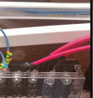
My own setup is a 1,000 W pure sine inverter on a 25 mm² run — roughly 2 AWG — over less than two metres, with an ANL fuse holder at the battery end.
By the table above I could have used less. I didn’t, for one reason: the cable is the only part of the installation you can’t upgrade later. The battery, the inverter, the controller — all of those you can swap in an afternoon. Once the furniture is built and the walls are closed, changing a cable means taking the van apart. The cable you fit in month two is the cable you live with.
And in my case that cable works in both directions.
When I connect an external power supply, the same 25 mm² pair that feeds the inverter carries current the other way to charge the battery. Most people size their inverter cable for discharge only and forget it may also be a charging path. If you run an inverter/charger, size for whichever current is higher — and remember the fuse has to cover both directions too.
The failure that taught me more than the gauge did
I had a charge controller terminal melt. Not because the cable was too thin — that cable was correctly sized — but because the terminal worked loose from road vibration.
A loose connection creates resistance at a single point. All the current in that circuit passes through it, and the heat concentrates in a few millimetres instead of spreading along a metre of copper. The cable stayed cool. The terminal cooked, discoloured, then deformed.
That’s the failure mode nobody calculates for. In a vehicle it’s more likely than an undersized cable, because a van shakes for hours at a time and a house doesn’t.
What I do now:
- Crimped ring terminals, not twisted-and-taped joints. A proper crimp is a gas-tight cold weld. A twisted joint is a resistance waiting to happen.
- Re-torque every terminal after the first thousand miles, then once a season. Things settle.
- Look before you touch. Discoloured metal, deformed plastic or a faint smell means it’s been running hot for a while.
- Check voltage across each connection, not just end to end. A bad terminal shows up as a step in the middle of an otherwise healthy run.
A perfectly sized cable with one bad terminal isn’t a good circuit. It’s a good circuit with a hot spot in it, and the hot spot is what fails.
Common mistakes
Measuring the straight-line distance. The cable doesn’t fly across the van — it routes around furniture, down conduit and behind panels. The real path is often double what you estimated by eye. Measure with a piece of string along the actual route before you buy.
Forgetting the return leg. Current goes out on the positive and comes back on the negative. A 6 ft installation is 12 ft of conductor, and both legs cause voltage drop. Every calculator on this page already accounts for it — but if you’re doing the maths by hand, don’t miss it.
Sizing for average draw instead of peak. Your fridge averages 50 W, but the compressor pulls 250 W at startup. Size for what the circuit actually has to carry at its worst moment.
Using automotive wire for house circuits. Standard automotive cable is often single-strand or low-strand-count and stiffens with vibration. Marine-grade tinned copper is finely stranded and resists corrosion. In a damp van that stands still for weeks, it’s worth the difference.
Doubling up thin cable instead of fitting the right one. Two 8 AWG cables in parallel are not a clean substitute for a 4 AWG. Current divides unevenly between them, and you’ve created two sets of terminals to work loose instead of one. Fit the correct size.
Fitting the fuse in the wrong place. The fuse protects the cable, not the appliance. It goes on the positive line as close to the battery as physically possible — ideally within a few inches. A fuse at the far end leaves the whole run unprotected against a short. If you’re not sure where fuses belong across the rest of the circuit, not just this cable, here’s the full layout.
Choosing the cable for the battery you have now. If there’s any chance you’ll add capacity or a bigger inverter later, size the cable for that. Running new cable through a finished build is the single most annoying job in van conversion.
Wire gauge for typical camper circuits
If you’d rather not calculate every circuit individually, this covers most van builds. Figures assume 12 V and a typical run length for that circuit — check anything unusually long against the calculator above.
| Circuit | Draw | Amps | Wire | Fuse |
|---|---|---|---|---|
| LED lighting run | 30-60 W | 3-5 A | 16 AWG | 10 A |
| USB outlets | 25 W | 2 A | 16 AWG | 5 A |
| Roof fan | 25-30 W | 2-3 A | 16 AWG | 10 A |
| Water pump | 60-90 W | 5-8 A | 14 AWG | 15 A |
| Compressor fridge | 40-60 W | 4-5 A (20 A peak) | 12 AWG | 15 A |
| Diesel heater | 100 W run | 10 A (glow plug) | 12 AWG | 20 A |
| Solar panels to controller (200 W) | 200 W | ~11 A | 10 AWG | 20 A |
| Controller to battery | 200 W | 15 A | 10 AWG | 25 A |
| DC-DC charger, 30 A | — | 30 A | 6 AWG | 40 A |
| DC-DC charger, 50 A | — | 50 A | 4 AWG | 60 A |
| Inverter, 1,000 W | 1,000 W | 98 A | 2 AWG | 125 A |
| Inverter, 2,000 W | 2,000 W | 196 A | 1/0 AWG | 250 A |
Note the fridge and the heater. Both are sized above what their running current suggests, because both have a brief high-current moment — a compressor starting, a glow plug firing. Size the wire and the fuse for that moment, not for the average.
One thing that confuses almost everyone
The output side of your inverter does not use cable like this. Once the inverter has converted 12 V DC into 120 V or 230 V AC, the current drops by a factor of ten or twenty. A 1,000 W load pulls 98 A on the battery side and about 8 A on the output side.
So the AC side uses ordinary household-style flexible cable, and the DC side uses cable as thick as your thumb. People routinely get this backwards — over-specifying the AC side, where it makes no difference, and under-specifying the battery run, where it decides whether the system works at all.
If you haven’t sized the inverter itself yet, do that first — the current it draws is what determines this cable. Inverter sizing calculator, including startup surge. Already know the inverter’s wattage? here’s the gauge broken down for 1000W, 1500W and 2000W units specifically.
Which type of cable to buy
Gauge is only half the decision. The other half is what the cable is made of, and here the differences matter more in a vehicle than in a building.
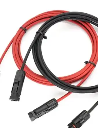
Marine-grade tinned copper. Finely stranded and tin-plated against corrosion. It’s the right answer for a van: fine strands survive constant vibration, and the tinning matters in a vehicle that sits damp for weeks at a time. It’s also the most expensive, roughly double automotive cable.
Automotive cable (GPT, TXL, SXL). Cheaper, coarser strands, not tinned. Fine for dry, well-protected runs — lighting, USB, switch wiring. TXL and SXL have thinner insulation, which helps in tight conduit runs. Not what I’d use for a battery cable or anywhere damp.
Welding cable. Very popular in US van builds for inverter runs, and it’s easy to see why: enormously flexible thanks to a very high strand count, and cheap per foot. But it’s usually bare copper rather than tinned, so it corrodes; the insulation isn’t rated for UV or oil; and it doesn’t meet ABYC standards, which matters if your build ever gets inspected. It’s a reasonable compromise for a short, dry, well-protected inverter run. I wouldn’t route it anywhere it can get wet.
Solid-core house wire (Romex, NM-B, or the equivalent in your country). Never in a vehicle. Solid conductors work-harden under vibration and eventually crack, usually inside the insulation where you can’t see it. This is the one genuine safety mistake on the list.
If you’re deciding on a budget: put the money into tinned marine cable for the battery runs and anything that gets damp, and use automotive cable for the light stuff. The battery cable is the one you can’t replace later and the one carrying enough current to start a fire.
Frequently asked questions
What size wire do I need for a 1000W inverter?
A 1,000 W inverter at 12 V draws around 98 amps. Over a short run of up to about 6 ft each way, that’s 4 AWG minimum, and 2 AWG is the safer choice. At 10 ft you need 2 AWG. Anything longer and you should consider relocating the inverter closer to the battery instead.
How do I calculate wire gauge for 12V?
Two calculations, and you take whichever gives the thicker wire. For voltage drop: circular mils = (10.75 × 2 × one-way length in feet × amps) ÷ allowable voltage drop. For ampacity, check the current rating of each gauge. Short runs are usually limited by heat, long runs by voltage drop.
What is an acceptable voltage drop in a 12V system?
Three per cent on critical circuits — inverters, fridges, water pumps, solar — which is 0.36 V at 12 V. Ten per cent is tolerable on non-critical circuits like lighting and USB outlets. The margin is small because most equipment cuts out below 10.5 V, and a battery at rest already sits near 12.6 V.
Can I use house wire in a camper van?
It’s not recommended. Solid-core household wire work-hardens and cracks under constant vibration, and it isn’t rated for the currents typical of 12 V circuits. Use finely stranded cable, and tinned marine-grade cable where damp is likely.
Does wire gauge matter for solar panels?
Yes, and it’s the most commonly missed run in a build. Panels are on the roof and the controller is usually low down, which makes it one of the longest cable paths in the van. Voltage drop there looks exactly like a panel that isn’t charging properly — more on that here.
Is thicker wire always better?
Electrically, yes — there’s no downside to oversizing beyond cost, weight and how hard it is to bend into tight spaces. Practically, one size up from the calculation is a sensible margin. Three sizes up just makes the terminals harder to crimp properly.
[…] ¿Prefieres verlo en inglés? Si tienes seguidores o dudas en inglés, aquí tienes la calculadora equivalente: Wire Gauge Calculator for 12V Systems: AWG by Amps and Cable → […]
[…] the amperage and the distance run — a fuse can’t compensate for undersized wire. Use the Wire Gauge Calculator for 12V Systems to get the right AWG for your amperage and run […]
[…] Wire Gauge Calculator for 12V Systems: AWG by Amps and Cable […]
[…] Wire Gauge Calculator for 12V Systems: AWG by Amps and Cable […]
[…] Important: these values are indicative. If the run between battery and inverter is long, you’ll need to size up. And if your inverter manufacturer recommends a specific gauge, that recommendation takes priority. For the general logic behind gauge sizing by amps and distance for any circuit — not just inverters — see the Wire Gauge Calculator for 12V Systems. […]
[…] Wire gauge calculator for 12V systems (AWG) […]
[…] Wire Gauge Calculator for 12V Systems: AWG by Amps and Cable […]
[…] Wire Gauge Calculator for 12V Systems: AWG by Amps and Cable […]